Documentation LED displays
1. Product presentation
- Numeric, alphanumeric or graphic
- Character size from 25 to 200mm
- 3 to 20 characters
- 1 to 2 lines
1.1 Options
- Integrated traffic lights
- Status LED
- Unit labels : kg, t, g, lb
- Power supply : 230V AC, 9-36V DC, PoE
- Communication : radio, TCP/IP, CAN, 4-20mA, TTY
- Wall, side or mast mounting
Note that these options are not available for all models. See the model summary table below.
1.2 List of products
| Family | Name |
|---|---|
| ER | ER-2004B |
| V10 | V10C |
| V10C-2004 | |
| V25 | V25N/G |
| V25N/E | |
| V60 | V60N-A |
| V60N-EX | |
| V100 | V100N |
| V100C | |
| V100C-1202 | |
| V100N-A-0301 | |
| V100N-0301 | |
| V100C-0301 | |
| V100C-0602 | |
| V100N-1001 | |
| V100C-1001 | |
| V100C-2002 | |
| V100N-A-0701 | |
| I100 | I100N |
| I100C | |
| I100C-1202 | |
| VLP | V100C-11x3 |
| V100C-11x10 | |
| A100 | A100 |
| A100-STOP | |
| V200 | V200N |
| V200G |
| Display | Mounting | Units | Power supply | Interface | ||||||
|---|---|---|---|---|---|---|---|---|---|---|
| Type | Resolution | Readability | Traffic light | Status indicators | Standard | Option | Standard | Option | ||
| Alphanumeric | 20 characters x 4 rows | 4 | no | no | Integration | 9-36V DC | 5V DC | RS232 | Radio, TCP/IP, CAN, CL, IO-Link | |
| Alphanumeric | 10 characters x 1 rows | 4 | no | yes | 12V DC | PoE | RS232 / RS485 | Radio, TCP/IP, CAN, CL, IO-Link, 4-20mA, 0-10V | ||
| Alphanumeric | 20 characters x 4 rows | 2 | no | yes | 12V DC | PoE | RS232 / RS485 | Radio, TCP/IP, CAN, CL, IO-Link, 4-20mA, 0-10V | ||
| Numeric | 6 characters x 1 rows | 12 | no | no | Wall | kg, t, g, lb, %vol | 9-36V DC | 5V DC, 230V AC | RS232 / RS485 | Radio, TCP/IP, CAN, CL, IO-Link, 4-20mA, 0-10V |
| Numeric | 6 characters x 1 rows | 12 | no | no | Integration | 9-36V DC | 5V DC, 230V AC | RS232 / RS485 | Radio, TCP/IP, CAN, CL, IO-Link, 4-20mA, 0-10V | |
| Numeric | 6 characters x 1 rows | 30 | yes | option | Wall, Pole, Lateral | kg, t, g, lb, %vol | 230V AC | 9-36V DC, PoE | RS232 / RS485 | Radio, TCP/IP, CAN, CL, IO-Link, 4-20mA, 0-10V |
| Numeric | 6 characters x 1 rows | 30 | no | no | Wall | 230V AC | 9-36V DC | RS232 / RS485 | Radio, TCP/IP, CAN, CL, IO-Link, 4-20mA, 0-10V | |
| Numeric | 6 characters x 1 rows | 50 | option | option | Wall, Pole, Lateral | kg, t, g, lb, %vol | 230V AC | 9-36V DC, PoE | RS232 / RS485 | Radio, TCP/IP, CAN, CL, IO-Link, 4-20mA, 0-10V |
| Alphanumeric | 6 characters x 1 rows | 50 | option | option | Wall, Pole, Lateral | kg, t, g, lb, %vol | 230V AC | 9-36V DC, PoE | RS232 / RS485 | Radio, TCP/IP, CAN, CL, IO-Link, 4-20mA, 0-10V |
| Alphanumeric | 12 characters x 2 rows | 22 | option | option | Wall, Pole, Lateral | kg, t, g, lb, %vol | 230V AC | 9-36V DC, PoE | RS232 / RS485 | Radio, TCP/IP, CAN, CL, IO-Link, 4-20mA, 0-10V |
| Numeric | 3 characters x 1 rows | 50 | yes | option | Wall, Pole, Lateral | kg, t, g, lb, %vol | 230V AC | 9-36V DC, PoE | RS232 / RS485 | Radio, TCP/IP, CAN, CL, IO-Link, 4-20mA, 0-10V |
| Numeric | 3 characters x 1 rows | 50 | no | option | Wall, Pole | kg, t, g, lb, %vol | 230V AC | 9-36V DC, PoE | RS232 / RS485 | Radio, TCP/IP, CAN, CL, IO-Link, 4-20mA, 0-10V |
| Alphanumeric | 3 characters x 1 rows | 50 | no | option | Wall, Pole | kg, t, g, lb, %vol | 230V AC | 9-36V DC, PoE | RS232 / RS485 | Radio, TCP/IP, CAN, CL, IO-Link, 4-20mA, 0-10V |
| Alphanumeric | 6 characters x 2 rows | 22 | no | option | Wall, Pole | kg, t, g, lb, %vol | 230V AC | 9-36V DC, PoE | RS232 / RS485 | Radio, TCP/IP, CAN, CL, IO-Link, 4-20mA, 0-10V |
| Numeric | 10 characters x 1 rows | 50 | option | option | Wall, Pole | kg, t, g, lb, %vol | 230V AC | 9-36V DC | RS232 / RS485 | Radio, TCP/IP, CAN, CL, IO-Link, 4-20mA, 0-10V |
| Alphanumeric | 10 characters x 1 rows | 50 | option | option | Wall, Pole | kg, t, g, lb, %vol | 230V AC | 9-36V DC | RS232 / RS485 | Radio, TCP/IP, CAN, CL, IO-Link, 4-20mA, 0-10V |
| Alphanumeric | 20 characters x 2 rows | 22 | option | option | Wall, Pole | kg, t, g, lb, %vol | 230V AC | 9-36V DC | RS232 / RS485 | Radio, TCP/IP, CAN, CL, IO-Link, 4-20mA, 0-10V |
| Numeric | 7 characters x 1 rows | 50 | yes | option | Wall, Pole | kg, t, g, lb, %vol | 230V AC | 9-36V DC | RS232 / RS485 | Radio, TCP/IP, CAN, CL, IO-Link, 4-20mA, 0-10V |
| Numeric | 6 characters x 1 rows | 50 | no | option | kg, t, g, lb, %vol | 230V AC | 9-36V DC, PoE | RS232 / RS485 | Radio, TCP/IP, CAN, CL, IO-Link, 4-20mA, 0-10V | |
| Alphanumeric | 6 characters x 1 rows | 50 | no | option | kg, t, g, lb, %vol | 230V AC | 9-36V DC, PoE | RS232 / RS485 | Radio, TCP/IP, CAN, CL, IO-Link, 4-20mA, 0-10V | |
| Alphanumeric | 12 characters x 2 rows | 22 | no | option | kg, t, g, lb, %vol | 230V AC | 9-36V DC, PoE | RS232 / RS485 | Radio, TCP/IP, CAN, CL, IO-Link, 4-20mA, 0-10V | |
| Alphanumeric | 11 characters x 3 rows | 50 | no | no | 230V AC | RS232 / RS485 | Radio, TCP/IP, CAN, CL, IO-Link | |||
| Alphanumeric | 11 characters x 10 rows | 50 | no | no | 230V AC | RS232 / RS485 | Radio, TCP/IP, CAN, CL, IO-Link | |||
| Traffic light | OO red / green | 50 | yes | option | Wall, Pole | 230V AC | 9-36V DC, PoE | RS232 / RS485 / Contacts | Radio, TCP/IP, CAN, CL, IO-Link | |
| Traffic light | STOP / -> | 50 | yes | option | Wall, Pole | 230V AC | 9-36V DC, PoE | RS232 / RS485 / Contacts | Radio, TCP/IP, CAN, CL, IO-Link | |
| Numeric | 6 characters x 1 rows | 100 | no | yes | Wall | kg, t, g, lb, %vol | 230V AC | 9-36V DC | RS232 / RS485 | Radio, TCP/IP, CAN, CL, IO-Link, 4-20mA, 0-10V |
| Grafics | 76x16 pixels | 100 | no | yes | Wall | kg, t, g, lb, %vol | 230V AC | 9-36V DC | RS232 / RS485 | Radio, TCP/IP, CAN, CL, IO-Link, 4-20mA, 0-10V |
2. Installation instructions
2.1 Safety and maintenance

Before opening the appliance, make sure that it is not powered up.
The display may not be used in areas with risk of explosion.
To clean, use only water or water with a mild liquid detergent.
Do not use detergents containing abrasive substances or solvents.
Do not clean with a high-pressure jet.
2.2 Enclosure
After unscrewing the cover, the electrical connection terminals are easily accessible. The terminal numbers are shown next to the terminal blocks.
Power cables or connectors can be removed to make installation easier.
To close the display, screw the cover back on, ensuring that the seal is firmly in place.
2.3 Cable gland
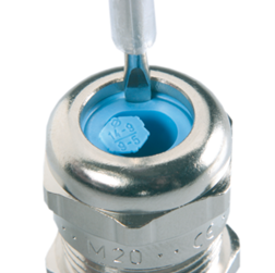
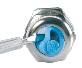
Remove the insert if the cable diameter is greater than 7mm. To do this, push the screwdriver in vertically and lever out the insert.
2.4 Electrical connections
V25
V60
V100 / V200
2.5 Optional features installation
Traffic light : see section “7. Traffic light control”
Radio module : see document 3501.500
TCP/IP Converter : see document 3501.505
Current loop, 4-20mA, 0-5V, 0-10V interfaces : see document 3501.519
4-20mA, 0-5V, 0-10V interfaces calibration : see document 3501.521
3. Integrated protocols
Many protocols are already implemented in the standard firmware. The table below describes all the built-in protocols.
3.1 Manufacturer protocols
| Manufacturer | Protocol | No. protocol | Number of characters to hide (H) | Data lenght (L) | Annunciators | Traffic Light | DIP Switch | ||||
|---|---|---|---|---|---|---|---|---|---|---|---|
1 |
2 |
3 |
4 |
S1 | S2 | ||||||
| ADN | 2 | 00 | |||||||||
| Agreto | VTEC Fernanzeige mit Ampel | 16 | 00 | 6 | Yes | ||||||
| Agreto | VTEC Fernanzeige ohne Ampel | 2 | 00 | 6 | |||||||
| AND Instruments | standard GROS | 3 | 72 | ||||||||
| AND Instruments | standard NET | 3 | 79 | ||||||||
| Avery/Berkel | L130 series | 0 | 00 | ||||||||
| Avery/Berkel | LC 115..217 series | 3 | 01 | ||||||||
| Avery/Berkel | LC210 series 2 Status Bytes | 0 | 02 | ||||||||
| Avery/Berkel | LC210 series 3 Status Bytes | 0 | 03 | ||||||||
| Averyweigh-tonix | 2 | 01 | |||||||||
| Bilanciai | standard und erweitert | 8 | ->0<- | Net | Error | Yes | |||||
| Consolidated Weight | Consolidated & RLWS series | 3 | 00 | ||||||||
| Dini Argeo | 39 | Net | 0 | ~ | Yes | Stability with traffic light | 0 | ||||
| Döhrn | 41 | Yes | |||||||||
| Dyona | 44 | Net | ->0<- | ~ | |||||||
| EHP | 27 | Net | Error | ||||||||
| EXA | ? | 33 | Net | ->0<- | |||||||
| EXA | C10/CN10 | 5 | 04 | ||||||||
| Flintab | 47-04/47-08 | 3 | 03 | ||||||||
| Flintec | 26 | Net | 0 | 0 | |||||||
| Flintec | 3 | 1 | 6 | ||||||||
| Flintec | 3 | 04 | |||||||||
| Fritz Kübler | Codix 56x und 57x | 30 | |||||||||
| Gassner | Pcout.V04 | 35 | ->0<- | Error | |||||||
| Gassner | DMA02 junior GROSS | 0 | 07 | ||||||||
| Gassner | DMA02 junior NET | 0 | 21 | ||||||||
| Gassner | DMA02 junior TARE | 0 | 14 | ||||||||
| Giropès | 51 | Net | ->0<- | ~ | |||||||
| GSE | 350/450/550/650 | 3 | 1 | ||||||||
| Haenni, CH | all models | 3 | 01 | ||||||||
| HBM | 2 | 03 or 04 | |||||||||
| Infratron | 3 | 01 | |||||||||
| Janner | 38 | ||||||||||
| Kölndata | 13 | Net | ->0<- | ~ | Data | Yes | |||||
| LaserMike Inc | Model 940 | 3 | 02 | ||||||||
| Laumas | 3 | 9 | 6 | ||||||||
| Leon Engineering | Model 5204/06 | 3 | 02 | ||||||||
| Maselli | 2 | 00 | 5 | ||||||||
| MasterK | IDe | 11 | Net | ->0<- | PT | Data | |||||
| MasterK | IDe | 25 | Net | ->0<- | PT | Data | Yes | ||||
| MasterK | IDM | 24 | ->0<- | Net | |||||||
| Mettler-Toledo | 8617/MultiCont1 | 26 | Net | 0 | 0 | ||||||
| Mettler-Toledo | 8624/MultiCont2 | 26 | Net | 0 | 0 | ||||||
| Mettler-Toledo | ID Series | 26 | Net | 0 | 0 | ||||||
| Mettler-Toledo | STX Older standard | 3 | 01 | ||||||||
| Mettler-Toledo | Toledo Continuous | 3 | 04 | ||||||||
| Mettler-Toledo | Toledo Continuous | 26 | Net | 0 | 0 | ||||||
| Millier | IDM2 | 11 | |||||||||
| Minebea | Protokoll V1.01 | 28 | Net | ->0<- | Error | ||||||
| Molen Weight | Molen Scales,NL series | 3 | 02 | ||||||||
| Norsk Display | Left justified STX-CR | 3 | 01 | ||||||||
| Norsk Display | Standard STX-CR 5 digits | 3 | 01 | ||||||||
| Norsk Display | Standard STX-CR 6 digits | 3 | 01 | ||||||||
| Pavone | DAT-400 | 4 | 01 | ||||||||
| Pfister | Bilanciai short+long formats | 3 | 02 | ||||||||
| Pfister | DFA 10 byte protocol format | 0 | 01 | ||||||||
| Pfister | FAZ 8 byte protocol format | 0 | 00 | ||||||||
| Pfister | standard und erweitert | 8 | ->0<- | Net | Error | Yes | |||||
| Philips | 1577/1627 Protocol | 0 | 03 | ||||||||
| Pivotex | Consolidated type | 3 | 03 | ||||||||
| Pivotex | Flintab type | 3 | 03 | ||||||||
| PPA | Cave | 29 | kg | % vol. | |||||||
| Precia Molen | A Plus | 10 | Net | ->0<- | |||||||
| Precia Molen | ABC | 10 | Net | ->0<- | |||||||
| Precia Molen | ABC | 3 | 01 or 13 | ||||||||
| PTM | 20 | Net | |||||||||
| PTM | Multilink | 0 | 34 | 6 | |||||||
| Raute Precision | WB-900 SERIES | 3 | 01 | ||||||||
| Ravas | 3100N/3200N | 3 | 0 | 7 | |||||||
| Ravas | 3100N/3200N/5200 | 22 | Net | ->0<- | ~ | Error | Net | ||||
| RHEWA | ANZEI.1 | 5 | 00 | ||||||||
| RHEWA | ANZEI.1 | 32 | Yes | ||||||||
| RHEWA | ANZEI.1 | 46 | Net | ->0<- | >< | ||||||
| Rice Lake Weighing System | 3 | 01 | |||||||||
| Rinstrum | Ranger A, Ranger B | 36 | |||||||||
| Sartorius | Protokoll V1.01 | 28 | Net | ->0<- | Error | ||||||
| Scaime | Protokoll Dini Argeo | 39 | Net | ~ | |||||||
| Scaime | RepeaterDC Protocol | 53 | Net | ->0<- | ~ | Yes | |||||
| Scaime | Modbus | 52 | Net | ->0<- | ~ | Display Net | |||||
| Schenck | DDP8861 | 12 | Net | ->0<- | Error | ||||||
| Schenck | DDP8861 modified | 12 | Net | ->0<- | Error | Yes | |||||
| Schenck | DDP8861 | 3 | 04 | ||||||||
| Schenck | DDP8861 | 3 | 05 | ||||||||
| Siebert | 0 | ? | |||||||||
| Siemens | SIWAREX | 43 | |||||||||
| Siloking | Spezialprotokoll mit Lauftext | 49 | |||||||||
| Sipi | 51 | Net | ->0<- | ~ | |||||||
| SMA | Scale Manufacturers Association Standard Scale Serial Communication Protocol | 21 | Net | ->0<- | ~ | Error | |||||
| Systec | erweitertes Standard-Protokoll
X........... |
2 | 10 | ||||||||
| Systec | Standard-Protokoll
'Daten |
2 | 06 | ||||||||
| Systec | Standard-Protokoll
'Daten |
16 | 05 | Yes | |||||||
| Systec | erweitertes Standard-Protokoll
X........... |
23 | Net | ->0<- | ~ | Data | Yes | ||||
| Thurman Scale | 465 Indicator | 3 | 01 | ||||||||
| Trayvou | VS-105 | 31 | Net | ->0<- | >< | ||||||
| Uni System | UNI U-127 Series | 3 | 1 | ||||||||
| Utilcell | Matrix | ||||||||||
| Vishay | Continuous Weight Output | 45 | Net | ->0<- | ~ | Data | |||||
| Vtec | Vtec protocol | 6 | Yes | ||||||||
| Vtec | DC-Interface | 48 | Net | Set low point | Set high point | ||||||
| Vtec | Demo | 55 | |||||||||
| Vtec | Test comunication | 54 | |||||||||
| Wöhwa | 50 | ||||||||||
3.2 Standard protocols
| Protocol | Protocol No. |
|---|---|
| <STX> data <ETX> | 000 |
| <STX> Addr data <ETX> | 001 |
| data <CR> <LF> | 002 |
| data <CR> | 003 |
| <STX> data <EOT> | 004 |
| <STX> data <CR> | 005 |
These standard protocols require you to specify the number of characters to be masked (H) and the length of the data (L).
3.3 Standard protocol with traffic light control
| Protocol | Protocol No. | Comments |
|---|---|---|
| <STX> data <ETX> | 014 |
Protocols identical to those above, but allows the lights to be activated by sending a character before the text to be displayed: ‘0’ = no light ‘1’ = red ‘2’ = green ‘3’ = red and green |
| <STX> Addr data <ETX> | 015 | |
| data <CR> <LF> | 016 | |
| data <CR> | 017 | |
| <STX> data <EOT> | 018 | |
| <STX> data <CR> | 019 |
4. Configuration
Parameters such as communication protocol and baud rate can be set in three ways: via the push-button, via serial line or from a PC. Each approach is described in the following sections.
4.1 Configuration using the button
The display is configured using the push-button located near the electrical connection terminals.
- To enter in the configuration mode, press the button until « CONFIG » is displayed, then release.
- To increment, press on the button less than 0.5 seconds.
- To decrement, press on the button between 0.5 and 1 second.
- To go to the next parameter, press on the button until “NEXT” appears, then release it.
- To exit the configuration mode, press on the button until “END” appears, then release. The display will
restart automatically.
4.1.1 General Reset
During configuration, it may be useful to perform a general ‘RESET’ to reconfigure the display to factory settings. Here are the steps for performing a RESET:
- Switch off the display.
- Press and hold the push button.
- Switch on the display.
- Release the button once ‘DEFAUL’ is displayed.
4.1.2 List of configuration values
| Parameter | Protocol (P) | Hidden characters (H) |
Display data length (L) |
Interface | Baud rate | Parity | Adress (A) |
Timeout (T) [s] |
Intensity (I) [%] |
|---|---|---|---|---|---|---|---|---|---|
| Value 1 | 000 | 0 | 0 | 232 | 300 | 8-Bit none | 001 | no timeout | max |
| Value 2 | 001 | 1 | 1 | 485 | 600 | 8-Bit, even | 002 | 5 | auto |
| Value 3 | 002 | 2 | 2 | 1200 | 8-Bit, odd | 003 | 10 | min | |
| Value 4 | 003 | 3 | 3 | 2400 | 7-Bit, none | 004 | 15 | 2 | |
| Value 5 | 004 | 4 | 4 | 4800 | 7-Bit, even | 005 | 20 | 3 | |
| Value 6 | 005 | 5 | 5 | 9600 | 7-Bit, odd | 006 | 25 | 4 | |
| Value 7 | 006 | 6 | 6 | 14400 | 007 | 30 | 5 | ||
| Value 8 | 007 | 7 | 7 | 19200 | 008 | 35 | 10 | ||
| Value 9 | 008 | 8 | 8 | 28800 | 009 | 40 | 20 | ||
| Value 10 | 009 | 9 | 9 | 38400 | 010 | 45 | 30 | ||
| ... | ... | ... | ... | ... | ... | ... | |||
| Max value | 055 | 55 | 55 | 127 | 60 | 95 |
4.1.3 Procedure for the A100 model
As the A100 model does not allow a letter to be displayed to show the parameters, it is necessary to print a mask below and place it on the display. Configuration is made possible by illuminating the parts of the mask corresponding to the parameters.
The configuration procedure is the same as for the digital displays.
4.2 Direct setup
This function is used to modify parameters via the existing transmission line.
This type of programming allows access to parameters that are not accessible using the pushbutton or the V1000DGA PC program.
To enable configuration, it is important that the RS232 or RS485 transmission frequency is the same as that configured in the display. It is therefore necessary to configure the display using the push-button to set the correct transmission frequency, see section “4. Configuration using the push-button”.
If the following character string is transmitted, the following data is interpreted as configuration data.
In ASCII : { \ _ @ # *
In HEX : 0x7B 0x5C 0x5F 0x40 0x23 0x2A
The parameters can now be transmitted. Each parameter must begin with an ESC character (0x1B) and end with a CR (0x0D).
Configuration mode ends when two successive CRs (0x0D) are sent. After this, the display automatically restarts with the new settings.
The diagram below shows the character sequence to be transmitted.
Please note: the new settings take effect once you exit programming mode.
4.2.1 List of parameters
The table below lists all the parameters available for configuration by serial line. The “Type” and “Data” columns contain the characters to be transmitted in ASCII code.
| Function |
Type [ASCII] |
Data [ASCII] |
Description | |
|---|---|---|---|---|
| Communication | S | 0 | RS485 | |
| 1 | RS232 | |||
| Define Baud rate | B | 0 | 300 | |
| 1 | 600 | |||
| 2 | 1200 | |||
| 3 | 2400 | |||
| 4 | 4800 | |||
| 6 | 9600 | |||
| 7 | 19200 | |||
| 8 | 28800 | |||
| 9 | 38400 | |||
| Parity bit | C | 0 | 8-bit none | |
| 1 | 8-bit even | |||
| 2 | 8-bit odd | |||
| 3 | 7-bit none | |||
| 4 | 7-bit even | |||
| 5 | 7-bit odd | |||
| RESET at next Power On | E | - | ||
| Protocol number | P | xxx | xxx = 000 to 999 | |
| Display address | A | xxx | xxx = 000 to 255 | |
| Characters to hide | V | xx | xx = 00 to 99 | |
| Decimal point position | K | 0 | 000000 | |
| 1 | 00000.0 | |||
| 2 | 0000.00 | |||
| 3 | 000.000 | |||
| 4 | 00.0000 | |||
| 5 | 0.00000 | |||
| LED light power | D | x |
Supported values of x : [0,1,2,3,4,5,6,7,8,9,A,B,C,D,E,F,Z] x = 0 -> off x = F -> max x = Z -> auto |
|
| Timeout | T | xxy |
xx = 00 to 99 (second) xx = 00 -> no timeout y = 0 -> display '--¦¦--' y = 1 -> display nothing |
|
| Defines authorised weight limit (extinctions) | J | Uxxx… | xxx… = lower weight limit | |
| Oxxx… | xxx… = upper weight limit | |||
| X | Reset interval => remove interval | |||
| GPIO | W | 0 | Configured as input | |
| 1 | Configured as output | |||
| '->0<-' symbol position | Z | 0 | No symbol '->0<-' | |
| 1 | '->0<-' symbol in position 1 | |||
| 2 | '->0<-' symbol in position 2 | |||
| 3 | '->0<-' symbol in position 3 | |||
| 4 | '->0<-' symbol in position 4 | |||
| Traffic lights and status indicatiors based on contact inputs | F | 0fsx | If RED = 0 and GREEN = 0, turn on f and s |
f : Traffic light (0=off, 1=red, 2=green, 3=green+red, 4=no change) s : Status indicators x : Display time minimum in seconds |
| 1fsx | If RED = 1 and GREEN = 0, turn on f and s | |||
| 2fsx | If RED = 0 and GREEN = 1, turn on f and s | |||
| 3fsx | If RED = 1 and GREEN = 1, turn on f and s | |||
| 4fsx | In timeout if RED = 0 and GREEN = 0, turn on f and s | |||
| 5fsx | In timeout if RED = 1 and GREEN = 0, turn on f and s | |||
| 6fsx | In timeout if RED = 0 and GREEN = 1, turn on f and s | |||
| 7fsx | In timeout if RED = 1 and GREEN = 1, turn on f and s | |||
| Alternative text depending on contact inputs | X | 0xxx… | If RED = 0 and GREEN = 0, display xxx... |
If xxx... none, normal display |
| 1xxx… | If RED = 1 and GREEN = 0, display xxx... | |||
| 2xxx… | If RED = 0 and GREEN = 1, display xxx... | |||
| 3xxx… | If RED = 1 and GREEN = 1, display xxx... | |||
| 4xxx… | In timeout if RED = 0 and GREEN = 0, display xxx... | |||
| 5xxx… | In timeout if RED = 1 and GREEN = 0, display xxx... | |||
| 6xxx… | In timeout if RED = 0 and GREEN = 1, display xxx... | |||
| 7xxx… | In timeout if RED = 1 and GREEN = 1, display xxx... | |||
|
Optional: define variable characters with the following sequence: <DC1> yy zz t yy = index of the first variable character zz = index of the last variable character t = minimum time, remains t seconds |
||||
4.3 PC configuration
For displays with firmware 6.6c or earlier, configuration can be carried out using the V1000DGA program, available here as a download.
5. Instructions for updating the firmware
The firmware is common to all types of display with the same number of characters.
If required, the firmware can be adapted on request.
Versions 6.0 and higher cannot be installed on displays with older firmware. If necessary, the controller circuit must be replaced.
Installing the update software
Copy the ‘MegaLoad.net’ file to your PC’s local hard drive.
Firmware update
- Copy the xxxxx.hex file to the PC’s local hard drive. If the file has a ‘.txt’ extension, it must be renamed to ‘.hex’.
- Switch off the display power supply.
- Connect the repeater to the PC via RS232 using the KadVPlus adapter. If you do not have this adapter, connect the RS232 bus to terminals 3 (GND), 4 (TX) and 5 (RX).
- Run the ‘MegaLoad’ program and select the xxxxx.hex file.
- Enter the COM port number and set the speed to 9600 baud.
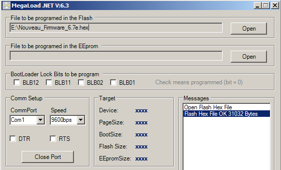
- Switch the display back on. Firmware loading should start automatically and is complete when the display restarts.
- If this did not happen automatically when the device was rebooted following the update, it is important to perform a general reset (hold down the configuration button when powering up and release it when the display shows ‘DEFAUL’).
6. Traffic light control
Traffic lights can be controlled in two ways:
1. Via potential-free contact inputs:
- The contact between terminal 8 (5V output) and terminal 6 (A-RED) switches on the red light.
- The contact between terminal 8 (5V output) and terminal 7 (A-GREEN) switches on the green light.
This is the default behaviour of lights based on contact inputs. This behaviour can be changed by modifying parameter ‘F’ per serial line, see section “5. Configuration per serial line”.
2. Via the protocol:
The protocols used to control lights are defined in the “Manufacturer Protocols” table in the “Traffic light” column.
6.1 Activation of TOR outputs
The two inputs with potential-free contacts can be converted into a digital output. The status of the lights transmitted via the communication protocol will be reported on the status of the two transistors.
Maximum current through the transistor : 200mA
Maximum voltage: 50V
To make this possible, a hardware modification and software configuration are required.

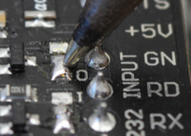
Hardware modification:
These changes must be made on both outputs (RED and GREEN).
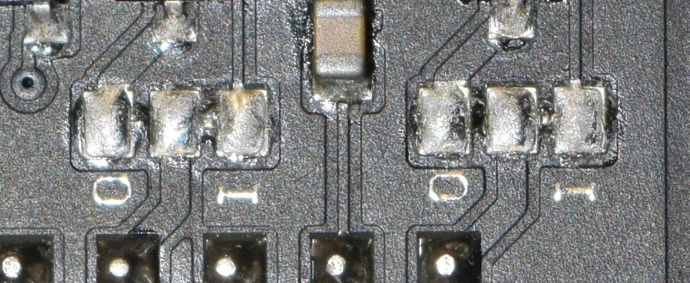
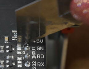
- Break the bond on the two “I” bridges. To do this, use a sharp tool to cut the bond between the two tin surfaces. Use an ohmmeter to check that the connection is correctly broken.
2. Make a soldering bridge with point “O”.
Software configuration:
To activate the digital outputs at software level, GPIO parameter ‘W’ must be set to output via serial line, as described in section “4.2 Direct setup”. The sequence to be transmitted is as follows:
In ASCII : { \ _ @ # * <ESC> W 1 <CR> <CR> <CR>
In HEX : 0x7B 0x5C 0x5F 0x40 0x23 0x2A 0x1B 0x57 0x31 0x0D 0x0D 0x0D
7. Dimensions / mechanical drawings
Select a model :
8. Mountings
Select a model and its mounting :
